
 2026.05.22
 Industry News
Content
PE electric fusion pipe clamps work by using embedded electrical resistance wires within a polyethylene (PE) fitting body to generate localized heat when an electric current is applied. This heat melts the inner surface of the clamp and the outer surface of the PE pipe simultaneously. The molten material from both surfaces fuses together under controlled pressure, and as the material cools, it forms a single, continuous, homogeneous molecular bond that is as strong as — or stronger than — the original pipe wall. The result is a fully sealed, leak-proof joint that cannot be separated without destroying the pipe itself.
This process, known as electrofusion welding, eliminates the mechanical weak points that exist in traditional mechanical clamp connections, such as gasket compression limits, bolt fatigue, and seal degradation over time. Because the bond is molecular rather than mechanical, electrofusion joints maintain their integrity across pressure cycles, temperature fluctuations, ground movement, and chemical exposure without requiring ongoing maintenance or periodic re-tightening.
Understanding the physics, sequence, and critical parameters of this working principle helps engineers, installers, and specifiers select the right products and apply them correctly for the specific demands of water supply, gas distribution, industrial pipeline, and infrastructure applications.
The working principle of PE electric fusion pipe clamps is grounded in the thermoplastic behavior of polyethylene and the precise application of resistive electrical heating. To understand why this method produces joints superior to mechanical alternatives, it is essential to understand what happens to PE at the molecular level during the fusion process.
Polyethylene is a thermoplastic polymer, meaning it softens and becomes viscous when heated above its melting point and returns to a solid state when cooled — without undergoing any chemical degradation in the process, provided the temperature is controlled correctly. The melting point of high-density polyethylene (HDPE), the grade most commonly used in pipe clamp fittings, is approximately 120°C to 140°C (248°F to 284°F). At these temperatures, the long polymer chains within the PE material gain sufficient thermal energy to move freely past one another, allowing the material to flow and intermingle across the interface between the clamp and the pipe surface.
When two PE surfaces are brought to this molten state simultaneously and held in contact under controlled pressure, the polymer chains from each surface migrate across the interface and entangle with chains from the opposing surface. Upon cooling, these entangled chains solidify into a unified structure with no distinguishable boundary between the two original materials — this is the molecular bond that gives electrofusion joints their exceptional strength.
The heat required to bring the PE surfaces to their melting point is generated by resistance heating wires embedded in the inner wall of the pipe clamp fitting during manufacturing. These wires — typically made from nichrome (nickel-chromium alloy) or stainless steel with diameters in the range of 0.3 to 1.0 mm — are positioned at a precisely controlled depth from the inner bore surface of the fitting, typically 1 to 3 mm below the surface. This positioning ensures that the heat is generated exactly where fusion needs to occur: at the interface between the fitting bore and the pipe's outer surface.
When an electric current from an electrofusion controller is passed through these wires, the electrical resistance of the wire converts electrical energy into thermal energy according to Joule's law: the heat generated is proportional to the square of the current multiplied by the resistance of the wire (Q = I² × R × t). The controller regulates the current, voltage, and duration of the heating cycle to deliver precisely the right quantity of thermal energy for the specific fitting size and design — enough to achieve full fusion without overheating the PE material to the point of degradation.
A critical but often overlooked element of the electrofusion working principle is the role of thermal expansion in generating the interface pressure needed for fusion. As the embedded wires heat the PE material of the fitting bore, the material expands. Because the pipe inserted into the fitting bore constrains this expansion, the expanding fitting material exerts an inward pressure on the pipe's outer surface. This self-generated contact pressure holds the molten interface surfaces together without any external clamping force being required during the heating cycle.
This is why electrofusion fittings must not be disturbed or moved during the heating cycle and the subsequent cooling period — any displacement of the pipe within the fitting breaks the uniform contact between the molten surfaces and produces a void or weak zone in the fusion zone. Most fitting manufacturers specify a minimum cooling time of 15 to 30 minutes before the joint may be pressure tested or subjected to any mechanical load, during which the thermal expansion pressure must be maintained undisturbed.
The physical design of PE electric fusion pipe clamps is engineered specifically to support the electrofusion process while addressing the practical requirements of field installation, storage, and long-term pipeline service. Each design element has a functional purpose tied to the working principle.
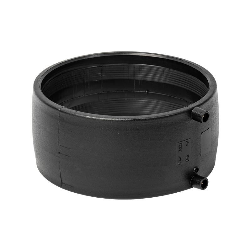
PE electric fusion pipe clamps are manufactured as solid cylindrical structures — a geometry that provides several functional advantages. The solid body creates a uniform mass of PE material surrounding the embedded resistance wire, which acts as a thermal reservoir that stabilizes the heating process and prevents localized overheating at any single point around the circumference. The cylindrical shape ensures that the fitting bore is perfectly round and concentric, so when a pipe is inserted, the contact between the clamp's inner surface and the pipe's outer surface is uniform around the full circumference — a necessary condition for producing a uniform fusion zone.
The smooth surface finish and rounded edges of the clamp body serve both practical and protective functions: they prevent damage to the pipe's outer surface during installation, reduce the risk of stress concentration points in the fitting body under service loads, and simplify cleaning and inspection of the fitting before use.
The resistance wire within a PE electric fusion pipe clamp is typically wound in a helical coil pattern around the full length of the fusion zone. This configuration ensures uniform heat distribution along the axial length of the joint and eliminates the temperature gradients that would occur if the wire were concentrated at a single point. The wire terminals emerge from the fitting body at standardized connection points — typically two pins positioned on one side of the fitting — which mate with the output connectors of the electrofusion controller.
The wire is encapsulated in PE material during the injection molding of the fitting, which fixes its position precisely and prevents any movement during the fusion cycle. The depth of the wire below the bore surface is a critical manufacturing parameter: too shallow and the wire may be exposed or create surface irregularities that prevent full pipe contact; too deep and the heat must travel too far through PE material before reaching the fusion interface, requiring higher energy input and longer heating times that increase the risk of material degradation in the outer fitting body.
Most PE electric fusion pipe clamps include visible fusion indicators — small observation ports or raised pins on the outer surface of the fitting that extrude outward as internal PE pressure builds during the heating cycle. These indicators serve as a visual confirmation that the fusion zone has reached the correct temperature and that sufficient material expansion has occurred to generate adequate interface pressure. Both indicators should have extruded visibly and to approximately the same height by the end of the heating cycle — asymmetric extrusion indicates uneven heating, which requires investigation before the joint is accepted.
Modern PE electric fusion pipe clamps incorporate a barcode or RFID tag that encodes the fitting's specific fusion parameters — including the required welding voltage, current, heating time, and cooling time — in a machine-readable format. The electrofusion controller reads this code at the start of each weld cycle and automatically configures itself to the correct parameters for that specific fitting. This eliminates the risk of operator error in setting incorrect fusion parameters and ensures that every fitting is welded under the exact conditions specified by its manufacturer.
The complete electrofusion welding cycle for a PE electric fusion pipe clamp proceeds through three distinct stages, each with specific time, temperature, and physical conditions that must be maintained for the joint to meet specification. Understanding each stage clarifies why the process produces such reliable results when correctly executed.
During the heating phase, the electrofusion controller applies a controlled electrical current to the fitting's resistance wire for a specified duration — the fusion time — that is determined by the fitting's size, wall thickness, and design. Typical fusion times range from 40 seconds for small-diameter fittings (20 to 32 mm) to several minutes for large-diameter fittings (200 mm and above).
During this phase, the resistance wire heats the surrounding PE material from the inside out. The heat conducts through the fitting bore wall to the pipe surface, raising both surfaces simultaneously above the PE melting point. The PE material at and near the interface transitions from solid to a viscous melt state, and the thermal expansion of the fitting material begins to generate the contact pressure between the fitting bore and the pipe surface.
The pipe must be held completely stationary throughout the heating phase. Any axial or rotational movement of the pipe within the fitting during this stage disrupts the forming melt interface and can introduce voids, inclusions, or incomplete fusion zones that are invisible from the outside but significantly reduce the joint's pressure rating and long-term reliability.
As the PE material at the fusion interface reaches its melt state, the continued thermal expansion of the fitting body drives the molten material from both surfaces together under increasing contact pressure. This is the phase during which polymer chain interdiffusion occurs — the molten PE chains from the fitting bore surface and from the pipe outer surface migrate across the interface and entangle with each other.
The degree of chain interdiffusion — and therefore the strength of the final bond — is directly related to the temperature at the interface and the time during which the interface is in its molten state. This is why the fusion time specified for each fitting is calculated to deliver exactly enough thermal energy to achieve complete chain interdiffusion across the full fusion zone width, without delivering so much energy that the outer fitting body begins to soften and lose its structural integrity.
When the electrofusion controller completes the heating cycle, it switches off the current to the resistance wire. The PE material at the fusion interface begins to cool from its melt state back toward solid. As it cools, the entangled polymer chains from both surfaces solidify together, creating a continuous solid with no internal boundary between the fitting material and the pipe material.
The cooling phase is as critical to joint quality as the heating phase. The joint must remain undisturbed for the full cooling time specified by the fitting manufacturer — typically 15 to 30 minutes at ambient temperatures above 10°C, and longer at lower temperatures. At low ambient temperatures, the cooling PE material contracts, and premature removal of the clamp support fixture or application of pipe loads during cooling can induce stress into the partially solidified fusion zone that manifests as microcracking or residual stress concentrations.
After the full cooling period, the resistance wire — now permanently embedded within the solidified joint — becomes a passive element of the joint structure. It plays no further active role but remains within the joint for the service life of the pipeline, which for PE pipelines in typical buried applications is rated at 50 years or more under design conditions.
The quality of an electrofusion joint is determined by a set of controllable and environmental parameters. Understanding which parameters are most critical — and how deviations from the correct values affect the joint — is essential for quality assurance in electrofusion pipeline construction.
| Parameter | Typical Specification | Effect of Under-Specification | Effect of Over-Specification |
|---|---|---|---|
| Fusion voltage | 8 V or 39.5 V (fitting-specific) | Insufficient heat; incomplete fusion; cold weld | Overheating; PE degradation; voids in fusion zone |
| Fusion time | 40 s to 1,800 s (diameter-dependent) | Incomplete chain interdiffusion; weak bond | Outer fitting body softening; dimensional distortion |
| Ambient temperature | -10°C to +45°C with correction | Rapid heat loss; insufficient interface temperature | Reduced cooling rate; extended required cooling time |
| Surface cleanliness | Zero contamination within fusion zone | Contamination barriers prevent molecular bonding | N/A — cleanliness cannot be excessive |
| Pipe scraping depth | 0.1–0.2 mm removal of oxidized layer | Oxidized layer prevents molecular bonding | Wall thickness reduction; potential stress concentration |
| Pipe insertion depth | Full insertion to centre stop mark | Partial fusion zone; unsealed end gap | N/A — most fittings have a physical stop |
| Cooling time | 15–30 min (temperature-dependent) | Premature loading of partially solidified joint | No negative effect — longer cooling is safe |
| Pipe ovality | Maximum 1.5% of nominal diameter | Uneven contact; localised fusion gaps | N/A — corrected by re-rounding clamp before fusion |
Ambient temperature significantly affects the rate at which heat is lost from the fusion zone to the surrounding environment during the heating phase. At low ambient temperatures — particularly below 0°C (32°F) — the rate of heat loss can be fast enough to prevent the interface from reaching the minimum fusion temperature during the standard heating time. Electrofusion controllers designed for field use include automatic ambient temperature correction algorithms that extend the heating time based on the measured ambient temperature, maintaining consistent thermal energy delivery to the fusion zone regardless of weather conditions. When working in temperatures below -10°C, additional measures such as windbreaks, pipe pre-warming, and extended minimum cooling times are required to achieve consistent joint quality.
Of all the factors that determine electrofusion joint quality, surface preparation of the pipe is the single most important variable under the installer's control. The working principle of electrofusion depends on direct polymer-to-polymer contact between clean, freshly exposed PE surfaces. Any contamination or oxidation at the interface acts as a barrier to polymer chain interdiffusion and produces a joint that may appear visually complete but lacks the molecular bond required for structural reliability.
All PE pipes exposed to air and UV light develop a thin oxidized surface layer — typically 0.1 to 0.3 mm thick — through photo-oxidation and thermal oxidation during extrusion and storage. This oxidized layer has a significantly different molecular structure from the virgin PE beneath it: the polymer chains are shorter, more cross-linked, and contain oxidized functional groups that do not interdiffuse effectively with the chains in the fitting bore PE. Attempting to electrofuse through an oxidized layer produces a joint in which the two PE surfaces bond with the oxidized layer rather than with each other — a structurally weak bond that can fail under pressure cycling or bending loads well below the design rating.
The oxidized layer must be completely removed from the pipe surface within the fusion zone using a rotary pipe scraper or abrasive tool that removes material uniformly to a depth of 0.1 to 0.2 mm. The scraping must be completed immediately before insertion into the fitting — within a practical window of approximately 30 minutes in clean, dry conditions. Re-oxidation of a freshly scraped PE surface begins within this timeframe, particularly in warm, sunny, or humid conditions, so no delay between scraping and weld commencement is acceptable.
After scraping, the pipe surface must be cleaned with a lint-free cloth or paper wipe dampened with isopropyl alcohol (IPA) of at least 99% purity. This removes any dust, moisture, grease, or contamination that may have landed on the freshly scraped surface. The cleaning wipe must be drawn in a single direction across the surface — not wiped back and forth — to avoid redistributing contamination. The surface must be allowed to dry completely before the pipe is inserted into the fitting, as residual solvent on the surface can prevent bonding or create steam voids during the heating phase.
The interior bore of the fitting must never be scraped, abraded, or cleaned with solvents — the fitting bore is manufactured to precise dimensions and surface conditions optimized for fusion, and any alteration of the bore surface can compromise the contact geometry and wire depth relationship that the fitting is designed around.
The effectiveness of PE electric fusion pipe clamps is not incidental — it is a direct consequence of the specific material properties of polyethylene that make it uniquely well-suited to electrofusion joining. Understanding these properties explains why PE is the dominant material for electrofusion pipeline systems globally.
High-density polyethylene is chemically inert to most common pipeline media, including potable water, natural gas, sewage, and a wide range of industrial chemicals. PE does not corrode, rust, or degrade from internal chemical attack, which means the fusion zone remains structurally intact over the pipeline's service life regardless of the media flowing through it. This contrasts with metallic pipe materials where corrosion at joints and fittings is a primary failure mechanism.
PE pipe clamp fittings are compounded with carbon black (typically at 2 to 2.5% by weight), which provides excellent protection against UV radiation — the primary cause of outdoor polymer degradation. Carbon black absorbs UV energy and converts it to heat before it can break the polymer chain bonds in the PE matrix, extending the outdoor service life of PE fittings significantly compared to unprotected polymers. This UV stability means that PE electric fusion pipe clamps can be stored outdoors before installation without quality degradation, and fittings used in exposed above-ground applications maintain their material properties throughout a design life of 50 years or more.
PE has a significantly lower elastic modulus than metals — approximately 800 to 1,000 MPa for HDPE compared to approximately 200,000 MPa for steel. This flexibility means that PE pipelines and their electrofusion joints can accommodate ground settlement, seismic movement, and thermal expansion and contraction without the brittle fracture failures that affect rigid metallic systems. The monolithic nature of electrofusion joints means that the joint moves with the pipe rather than acting as a rigid fixed point — a critical advantage in geologically active areas and in applications where soil movement or thermal cycling is expected.
PE pipe materials are classified by their minimum required strength (MRS) at 20°C after 50 years of continuous internal pressure, as determined by long-term hydrostatic pressure testing. Current generation PE 100 material — the standard for pressure pipeline applications — has an MRS of 10 MPa (100 bar). Properly made electrofusion joints in PE 100 pipe achieve at least this rated strength, meaning the joint does not represent a weak point in the pipeline system — the pipe body and the electrofusion joint have equivalent pressure ratings under equivalent conditions.
The working principle of PE electric fusion pipe clamps makes them suitable for a wide range of pipeline applications where joint reliability, chemical resistance, and long service life are required. The following are the primary application sectors where this technology is specified and deployed.
Understanding how the electrofusion working principle positions PE electric fusion pipe clamps relative to alternative joining methods helps engineers and specifiers make informed choices for their specific project requirements.
| Criterion | Electrofusion (PE Clamp) | Butt Fusion Welding | Mechanical Compression Fitting | Flanged Connection |
|---|---|---|---|---|
| Bond type | Molecular fusion | Molecular fusion | Mechanical seal | Mechanical gasket |
| Joint strength vs. pipe | Equal or superior | Equal or superior | Lower — depends on compression | Lower — depends on bolt torque and gasket |
| Required workspace | Minimal — fits in confined spaces | Requires pipe end access and alignment | Minimal | Requires bolt access around full circumference |
| Operator skill required | Moderate — preparation critical | High — machine setup and alignment | Low to moderate | Moderate — torque control needed |
| Maintenance requirement | None — permanent bond | None — permanent bond | Periodic re-tightening may be needed | Periodic bolt retorquing and gasket inspection |
| Design service life | 50+ years | 50+ years | Variable — gasket dependent | Variable — gasket and bolt dependent |
| Suitability for repair in trench | Excellent | Limited — needs full pipe end access | Good | Poor — requires large excavation |
Because the molecular bond formed during electrofusion is invisible from the outside once the joint has cooled, quality assurance relies on a combination of process control, visual verification of the fusion indicators, and post-fusion testing where required by the project specification.
Modern electrofusion controllers produce a printed or digital record for each weld that captures the fitting identification, weld date and time, operator ID, actual voltage applied, actual weld duration, ambient temperature, and any fault conditions detected during the cycle. These records form the quality assurance documentation for the pipeline and allow any problematic joint to be traced back to its specific installation conditions if a failure occurs in service. On projects with formal quality requirements, controllers must be calibrated annually, operators must hold current electrofusion welding certification, and weld records must be retained for the pipeline's design life.
Several non-destructive testing methods can be applied to completed electrofusion joints to verify their internal quality without destroying the joint:
On projects or during operator qualification procedures, electrofusion joints are subjected to destructive tests to directly verify fusion quality. Common destructive tests include the peel test (where the fitting is peeled away from the pipe to expose the fusion interface) and the tensile test (where the joint is pulled to failure to determine whether the failure occurs through the fusion zone or through the parent pipe material). A correctly made electrofusion joint always fails through the parent pipe material in tensile testing, not through the fusion zone — fusion zone failure indicates an inadequate bond and requires investigation of the welding process parameters and surface preparation procedure.
Recommended Products
 General Manager Mr.Song +86-18868665013 / Miss Zhou +86-13757458992
 International Sales Manager: Jim Yao +86-18968349877
 +86-574-62939789
 Wechat/WhatsApp: +86-18968349877
 [email protected]; [email protected]
 No. 147 Dushan, Sanqi Town, Yuyao City, Zhejiang Province
Copyright © Ningbo Heqi Pipe Co., Ltd. All rights reserved. Wholesale Drainage Pipes Manufacturer Drainage Fittings Supplier


 EN
EN

 English
 中文简体
中文简体


