
 2026.05.15
 Industry News
Content
Drainage electrofusion fittings work by using embedded electrical resistance wires inside the fitting socket to generate precise, controlled heat when an electric current is applied. This heat melts the inner surface of the fitting and the outer surface of the pipe simultaneously, fusing them into a single, continuous, homogeneous joint. The result is a leak-proof, structurally strong connection that meets the demands of modern drainage systems — with a leakage rate of less than 1%, far surpassing traditional mechanical or solvent-welded methods.
Unlike conventional jointing techniques that rely on external heat sources, adhesives, or compression, electrofusion is a self-contained, repeatable process governed by standardized electrical parameters. Understanding how these fittings work helps engineers, contractors, and installers make better decisions in pipeline design, installation, and maintenance.
At the heart of every electrofusion fitting is a coil of resistance wire — typically made from nickel-chromium alloy — embedded within the inner wall of the fitting socket during manufacturing. When the fitting is connected to an electrofusion control unit and power is applied, the wire heats up according to Joule's Law (heat = I² × R × time).
The heat generated causes the surrounding polyethylene (PE) material to soften and melt. Simultaneously, the outer surface of the inserted pipe also begins to melt. As both molten surfaces merge under slight mechanical pressure from the cooling and shrinkage of the fitting, polymer chains from the fitting and pipe interlock at the molecular level, forming a bond that is chemically and structurally indistinguishable from the parent material.
This is not adhesion — it is true fusion. The joint, once cooled, carries the same material properties as the pipe itself, including pressure resistance, chemical resistance, and flexibility.
The electrofusion process follows a precise sequence. Each stage is critical to achieving a high-integrity joint:
The PE electrofusion pipe fittings series includes a broad range of components designed to handle virtually every geometric configuration and connection requirement in drainage systems:
| Fitting Type | Primary Function | Typical Application |
|---|---|---|
| Electrofusion Coupling / Pipe Clamp | Straight pipe-to-pipe joining | Extending pipe runs, repair of damaged sections |
| Electrofusion Tee | Branch connections at 90° | Distribution networks, lateral drain connections |
| Electrofusion Elbow | Direction change (45° or 90°) | Navigating around obstacles, vertical-to-horizontal transitions |
| Electrofusion Eccentric Reducer | Connecting pipes of different diameters | System transitions, flow management |
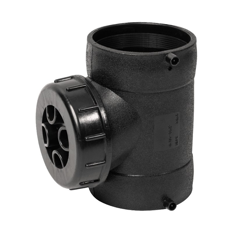
| Inspection Port Fitting | Access point for cleaning and camera inspection | Long drain runs, below-ground drainage systems |
All of these fitting types operate on the same electrofusion principle, with each embedding resistance wire coils matched to the specific geometry and wall thickness of the fitting. Standardized geometric dimensions ensure compatibility across pipe series and simplify procurement and installation.
The electrofusion controller is an essential part of the system. Modern controllers are microprocessor-based and offer automatic parameter management, significantly reducing the risk of human error. Key functions include:
Controllers typically output between 8V and 48V DC, with the most common standard in drainage applications being 40V. Some compact systems use 12V for small-diameter fittings used in residential installations.
Comparing electrofusion to conventional joining methods reveals clear advantages across multiple dimensions:
| Criterion | Electrofusion | Butt Fusion | Rubber Ring Joint | Solvent Cement |
|---|---|---|---|---|
| Leakage Rate | <1% | <2% | 5–10% | 3–8% |
| Space Required | Minimal | Moderate | Minimal | Minimal |
| Use of Chemicals / Welding Agents | None | None | None | Yes (VOC risk) |
| Skill Level Required | Low–Medium | High | Low | Medium |
| Suitable for Confined Spaces | Yes | No | Yes | Yes |
| Long-Term Structural Integrity | Excellent | Excellent | Moderate | Good |
The absence of welding agents or adhesives is particularly significant for drainage applications. Solvent cements can introduce contaminants into wastewater or stormwater systems, raise regulatory compliance concerns, and create health and safety hazards during installation in confined spaces. Electrofusion eliminates all of these risks.
The effectiveness of electrofusion depends heavily on the properties of the PE material used in both the fitting and the pipe. The most commonly specified grades for drainage electrofusion fittings are PE80 and PE100, both of which exhibit the thermoplastic behavior necessary for clean, repeatable fusion cycles.
The standardized geometric dimensions of electrofusion fittings — specifying socket depth, outer diameter tolerances, and wall thickness — ensure that the pipe-to-fitting interface dimensions match precisely, giving the resistance wire coil the correct contact pressure and gap to perform optimally.
One of the most valuable features of electrofusion fittings is the built-in visual and electronic quality control system. Installers and inspectors can verify joint quality through several methods:
Most electrofusion fittings incorporate indicator pins (also called spy holes or witness holes) on the outer surface. When fusion pressure is correctly achieved, the melted PE pushes these pins outward, confirming that the internal void has been filled with fused material. A flush or raised pin after cooling indicates a successful weld; a recessed or absent movement may signal incomplete fusion.
These layered quality assurance mechanisms make electrofusion one of the most auditable jointing technologies available, a key advantage for utility companies, municipal contractors, and regulatory bodies that require traceable records of every weld in a pipeline system.
Electrofusion can be performed across a wide range of environmental conditions, provided basic precautions are taken:
Understanding what can go wrong with electrofusion joints — and how the fitting design mitigates these risks — is essential for reliable installation:
| Failure Mode | Root Cause | Prevention by Design or Process |
|---|---|---|
| Cold fusion / incomplete bond | Insufficient voltage or fusion time | Controller auto-reads fitting parameters via barcode; temperature correction algorithm |
| Oxidized interface (poor adhesion) | Failure to scrape pipe outer surface | Training protocols; pipe scraper tools; checklist-based installation procedures |
| Displacement during cooling | No clamp or premature clamp removal | Mandatory clamping fixtures; controller cooling timer prevents early release |
| Contamination-induced void | Oil, grease, or moisture on pipe surface | Isopropyl alcohol cleaning; fitting storage seals; no-touch zones on prepared surfaces |
| Wire short circuit | Mechanical damage to fitting or contamination bridging coils | Controller resistance check at cycle start; visual fitting inspection before installation |
Drainage electrofusion fittings are used across a wide spectrum of infrastructure and building services applications, wherever reliable, long-life PE pipework is required:
In all of these settings, the high-strength, low-leakage, and chemically inert joint produced by electrofusion technology translates directly into reduced lifecycle costs, lower maintenance frequency, and greater confidence in system performance over the typical 50-year design life of PE pipework.
Drainage electrofusion fittings are manufactured and tested in accordance with a range of international standards that govern dimensions, material grades, and joint performance:
Compliance with these standards provides procurement teams, project engineers, and regulatory inspectors with assurance that the fittings have been tested to defined performance levels and that dimensional compatibility across manufacturers is maintained. Standardized fitting dimensions also allow different pipe and fitting batches from the same standard family to be interchanged on site without compatibility issues, simplifying logistics and reducing project delays.
 General Manager Mr.Song +86-18868665013 / Miss Zhou +86-13757458992
 International Sales Manager: Jim Yao +86-18968349877
 +86-574-62939789
 Wechat/WhatsApp: +86-18968349877
 [email protected]; [email protected]
 No. 147 Dushan, Sanqi Town, Yuyao City, Zhejiang Province
Copyright © Ningbo Heqi Pipe Co., Ltd. All rights reserved. Wholesale Drainage Pipes Manufacturer Drainage Fittings Supplier


 EN
EN

 English
 中文简体
中文简体


