 2026.06.26
 Industry News
Content
A PE siphon drainage pipe is a high-density polyethylene (HDPE or PE) pipeline system engineered to operate under negative pressure (vacuum conditions) to rapidly evacuate large volumes of rainwater from rooftops, paved surfaces, and industrial structures. Unlike conventional gravity drainage systems that rely on a sloped pipe partially filled with water, a siphon drainage system runs completely full of water, using the weight of the downpipe water column to create a sustained vacuum that draws water from the collection point at high velocity. The result is a dramatically more efficient drainage system that requires fewer, smaller pipes and handles peak storm flows that would overwhelm a traditional gravity system.
The siphon drainage principle relies on Bernoulli's equation and the concept of a hydraulic siphon. At system startup, specially designed anti-vortex roof outlets prevent air from entering the pipe as rainwater accumulates. Once the pipe fills completely with water and all air is purged, the weight of the water column in the vertical downpipe creates a negative pressure — effectively a vacuum — at the collection point. This negative pressure draws more water into the system at velocities typically between 2.5 and 7 meters per second, compared to 0.6 to 1.5 m/s in conventional gravity systems. (Source: Siphonic Roof Drainage Design Guide, HR Wallingford, UK, 2000)
Because the horizontal collection pipes run completely full of water under negative pressure, they do not need to be laid to a gradient. This is a fundamental design advantage: horizontal runs can be installed at or close to level, dramatically reducing the structural depth required beneath a roof slab or floor.
The combination of sustained negative pressure, high flow velocity, and temperature cycling that characterizes siphon drainage operation places specific and demanding requirements on the pipe material. PE — specifically HDPE to PE100 grade — meets all of these requirements in a single material that no alternative matches across the full range.
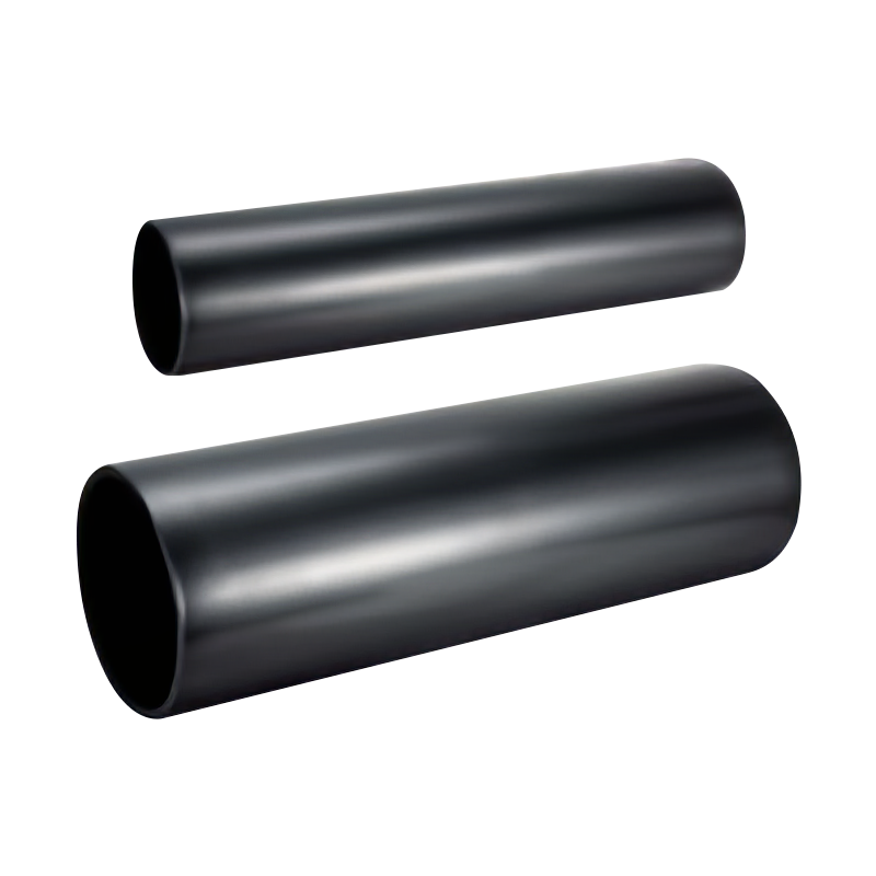
HDPE PE100 pipe to ISO 4427 has a minimum required strength (MRS) of 10 MPa and is rated for sustained internal pressures at the operating temperature range of siphon systems (-20 to +60 degrees Celsius). Critically, PE pipe resists collapse under external atmospheric pressure or negative internal pressure through a combination of wall thickness and material ductility that rigid materials such as uPVC cannot match at the same wall thickness. (Source: ISO 4427-1:2019, Plastics Piping Systems — PE Pipes and Fittings for Water Supply)
PE has a coefficient of thermal expansion of approximately 0.2 mm per meter per degree Celsius — significantly higher than steel or cast iron but well accommodated in siphon system design through expansion loops and anchoring. The flexibility of PE pipe means thermal movement is absorbed without cracking or joint failure, which is a persistent problem with rigid pipe materials in large roof installations exposed to seasonal temperature swings of 60 degrees or more. (Source: Plastics Pipe Institute, Engineering Technical Note PE-N-12, Thermal Expansion and Contraction in Polyethylene Piping Systems, 2012)
Roof drainage carries not only rainwater but also dissolved pollutants, bird waste, cleaning chemicals, and in industrial settings, process contamination. PE100 is chemically inert to the full range of substances encountered in roof drainage, does not support biological growth on its smooth inner bore, and does not corrode or scale over time. This gives PE siphon drainage pipe a design service life of 50 years or more in standard roof drainage applications without internal lining or treatment. (Source: German Institute for Standardization DIN 8075, Polyethylene Pipes — General Quality Requirements and Testing, 2011)
PE pipe has a Manning roughness coefficient of n = 0.009, one of the lowest of any pipe material. This smooth bore minimizes friction losses through the system, which is directly important in siphon drainage because friction loss in the horizontal collection pipework reduces the available vacuum head for driving flow. Lower friction loss means more efficient systems with smaller pipe diameters for equivalent flow rates compared to rougher materials.
| Feature | PE Siphon Drainage System | Conventional Gravity Drainage |
|---|---|---|
| Flow principle | Full-bore flow under negative pressure | Partial-bore flow under gravity |
| Pipe gradient required | None — horizontal runs laid level | Minimum 1:100 to 1:40 fall required |
| Flow velocity | 2.5 to 7.0 m/s | 0.6 to 1.5 m/s |
| Pipe diameter for equivalent flow | Smaller — 40% to 60% of gravity system size | Larger diameter required |
| Number of downpipes required | Fewer — one system serves large roof area | More downpipes, shorter spacing |
| Structural depth below roof slab | Minimal — level runs need little depth | Significant — gradient requires depth |
| Self-cleaning | Yes — high velocity prevents sediment | Risk of sediment at low gradient sections |
| Suitable for large flat roofs | Ideal | Difficult — gradient across large area is costly |
A study of warehouse and logistics facility construction in Germany found that siphon roof drainage systems reduced the total number of drainage penetrations through the roof membrane by up to 70% compared to conventional gravity systems on the same building footprint, significantly reducing both installation cost and long-term waterproofing maintenance risk. (Source: Fraunhofer Institute for Building Physics, Roof Drainage Systems Comparative Study, IBP Report, 2016)
The advantages of siphon drainage become most significant when the roof area is large, flat, or has limited fall for drainage pipework. Typical applications include:
PE siphon drainage pipe systems are specified to international standards that define material grade, pressure rating, dimensional tolerances, and joint integrity requirements:
| Parameter | Typical Specification | Standard Reference |
|---|---|---|
| Material grade | PE100 (MRS 10 MPa) | ISO 4427-1:2019 |
| Pipe SDR class | SDR11 to SDR26 (PN6.3 to PN16) | ISO 4427-2:2019 |
| Diameter range | DN40 to DN315 (typical siphon systems) | Project specific |
| Operating pressure range | -0.9 bar (vacuum) to +10 bar positive | System design to BS EN 12056-3 |
| Temperature range | -20 to +60 degrees Celsius continuous | ISO 4427-1 |
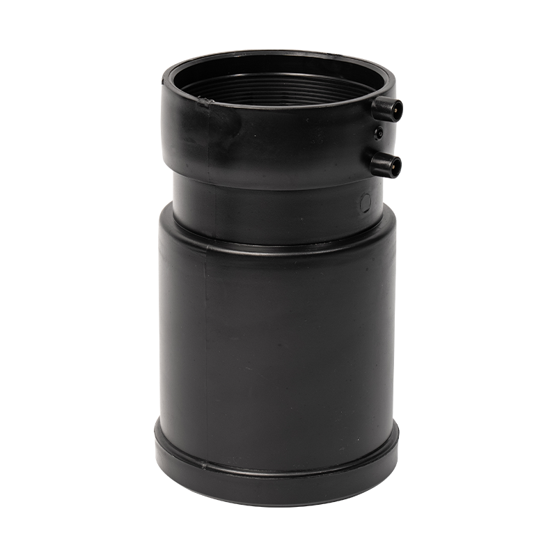
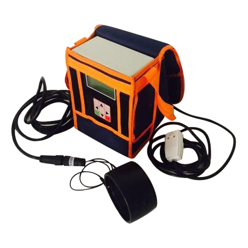
| Joint method | Electrofusion or butt fusion welding | ISO 11414, ISO 21307 |
| Design service life | 50 years minimum | ISO 9080 extrapolation |
The Heqi PE Siphon Drainage Pipe Series is manufactured to PE100 grade with dimensional compliance to ISO 4427 and is available in the full range of SDR classes and diameters required for siphon roof drainage system design. The pipes are produced for compatibility with electrofusion and butt fusion jointing systems, ensuring installation meets the leak-free joint integrity that siphon drainage demands under sustained vacuum operation.
A siphon drainage system requires careful hydraulic design that differs fundamentally from conventional drainage. Key design and installation points include:
Each outlet in a siphon system must contribute an equal share of the design flow to maintain balanced vacuum across the collection pipework. Unbalanced systems result in some outlets operating below the full-bore threshold, admitting air and collapsing the siphon effect. Hydraulic design software is used to size each pipe segment to achieve balanced pressure loss across all outlet branches simultaneously. (Source: BS EN 12056-3:2000, Gravity Drainage Systems Inside Buildings — Roof Drainage Layout and Calculation)
PE pipe in a large roof drainage system may experience temperature swings of 50 to 60 degrees Celsius between summer peak and winter minimum. On a 30-meter horizontal run, this generates thermal movement of approximately 360 mm that must be accommodated through a combination of expansion loops, sliding guides, and fixed anchor points. Anchor loads from the thermal forces in PE100 pipe must be incorporated into the structural design of the supporting steelwork.
A siphon system must be tested after installation to confirm that all air is purged from the collection pipework before the system is declared operational. Residual air pockets prevent full-bore flow from establishing, reducing system capacity and creating pressure cycling that stresses pipe joints. Commissioning typically involves flow testing under controlled rainfall simulation to verify that design flow rates and vacuum pressures are achieved at all outlets simultaneously.
| Aspect | Summary |
|---|---|
| What it is | HDPE pipe system operating under negative pressure for high-velocity roof drainage |
| Core advantage | No gradient required; smaller pipes; fewer downpipes; handles peak storm flows |
| Material grade | PE100 to ISO 4427, SDR11 to SDR26 |
| Operating pressure | -0.9 bar vacuum to +10 bar positive pressure |
| Flow velocity | 2.5 to 7.0 m/s (vs. 0.6 to 1.5 m/s for gravity systems) |
| Service life | 50 years or more in standard roof drainage service |
| Best suited for | Large flat roofs, airports, stadia, warehouses, green roofs, car park decks |
| Joint method | Electrofusion or butt fusion welding for leak-free vacuum-rated joints |
The bottom line: a PE siphon drainage pipe system is the engineered solution of choice wherever conventional gravity drainage cannot deliver the required capacity within the structural and architectural constraints of a large modern building. Its combination of hydraulic efficiency, PE100 material durability, and installation flexibility makes it the standard for major commercial and industrial roof drainage projects worldwide.
 General Manager Mr.Song +86-18868665013 / Miss Zhou +86-13757458992
 International Sales Manager: Jim Yao +86-18968349877
 +86-574-62939789
 Wechat/WhatsApp: +86-18968349877
 [email protected]; [email protected]
 No. 147 Dushan, Sanqi Town, Yuyao City, Zhejiang Province
Copyright © Ningbo Heqi Pipe Co., Ltd. All rights reserved. Wholesale Drainage Pipes Manufacturer Drainage Fittings Supplier



 EN
EN

 English
 中文简体
中文简体